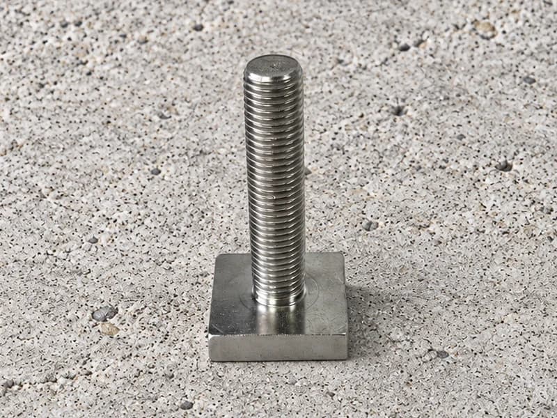
Square Head T Bolts
Externally threaded fasteners with a square flat head. Define the head footprint, thread and shank dimensions to suit the specified mating assembly.
View product →
Swipe to explore the product views.
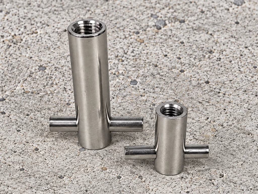
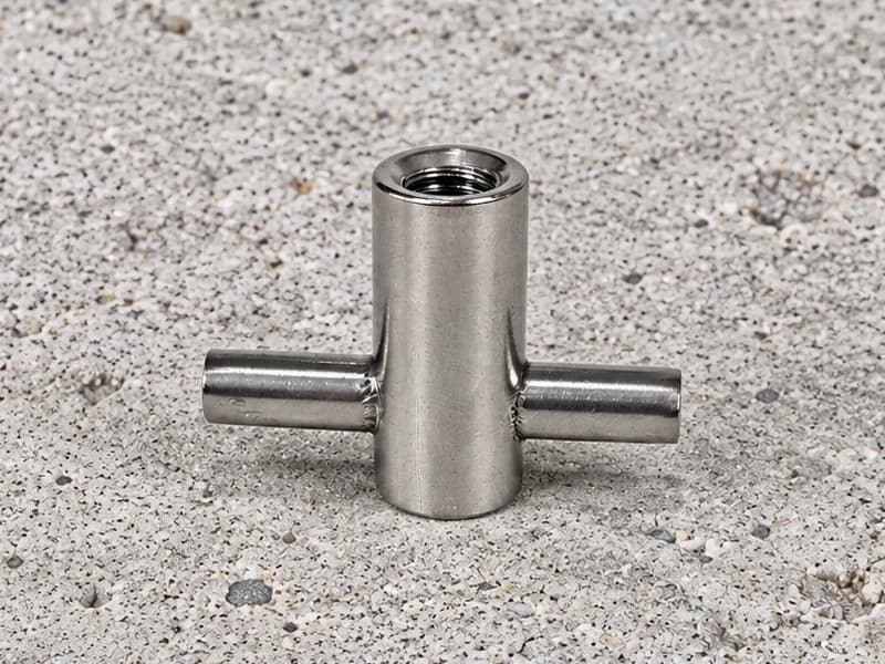
Internally threaded fixing inserts with a transverse pin projecting from both sides. Define the pin location, projection and joining requirements by drawing.
Share your drawing, material specification and quantity.
Cross-pin fixing inserts combine a threaded cylindrical body with a transverse pin near the lower end. The projecting pin distinguishes this form from footed ferrules and from sockets with an empty cross-hole. Define the body proportions and the pin arrangement together to establish the component required for your project.
The drawing should identify the pin diameter, total length, projection on each side and position relative to the socket end. Where pin centring or orientation is important, include the relevant datum and acceptance tolerance.
Define how the pin is retained or joined to the body and which inspection evidence is required. A photograph does not establish weld quality, an interference fit or the internal construction of the body. Likewise, a transverse pin is not evidence that an insert is approved for a particular load or installation.
For a fixing-insert inquiry, provide the mating thread details and the surrounding component arrangement. Identify the intended duty and the required project documents so the manufacturing review addresses a defined connection component.
Specify the material for both the body and pin, together with the acceptance requirements for their connection. Any required performance validation is a separate part of the project scope; no lifting rating is included with this component description.
Tolerances, order quantity and lead time are assessed for the project.
Send your drawing →The illustrated insert includes a pin projecting through the body. A cross-hole socket has an opening for a separately specified bar; the supplied components and their requirements are different.
No replacement is established by this description. The fixing arrangement and any reinforcement requirements must follow the approved project design.
No lifting rating is stated. Any lifting use would require a separately defined and validated component and assembly specification.
Share your drawing and requirements. Let’s discuss the manufacturing route.
Compare other component forms for your drawing requirements.
Externally threaded fasteners with a square flat head. Define the head footprint, thread and shank dimensions to suit the specified mating assembly.
View product →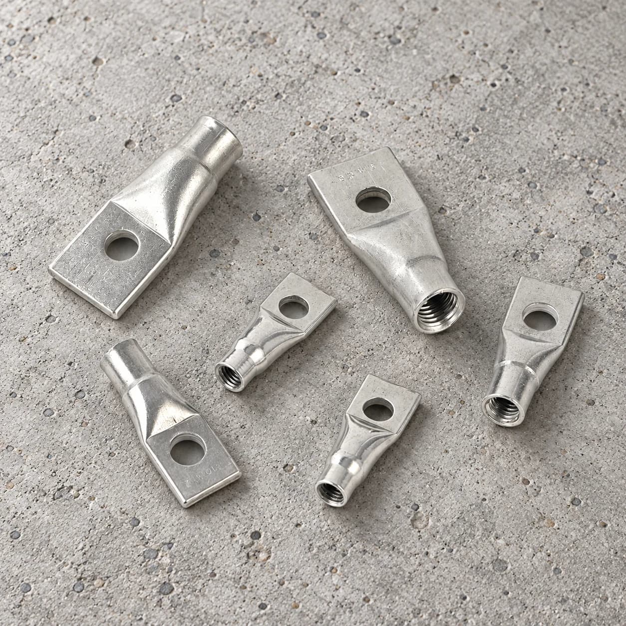
Threaded socket forms with a flattened end and transverse hole. Define the hole position, flat-section dimensions and internal thread for your project.
View product →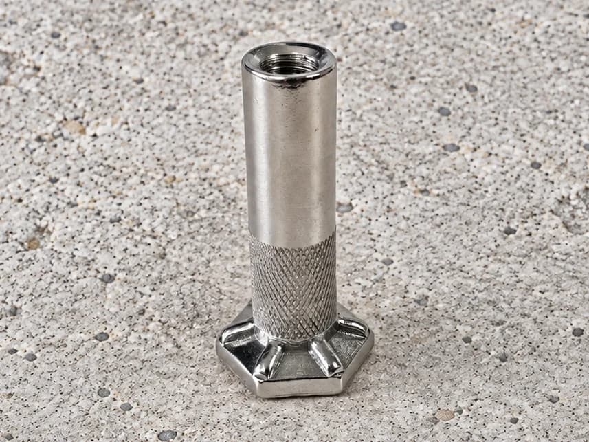
Internally threaded ferrules with a hexagonal foot. Define the body length, thread engagement and base geometry for your concrete connection project.
View product →