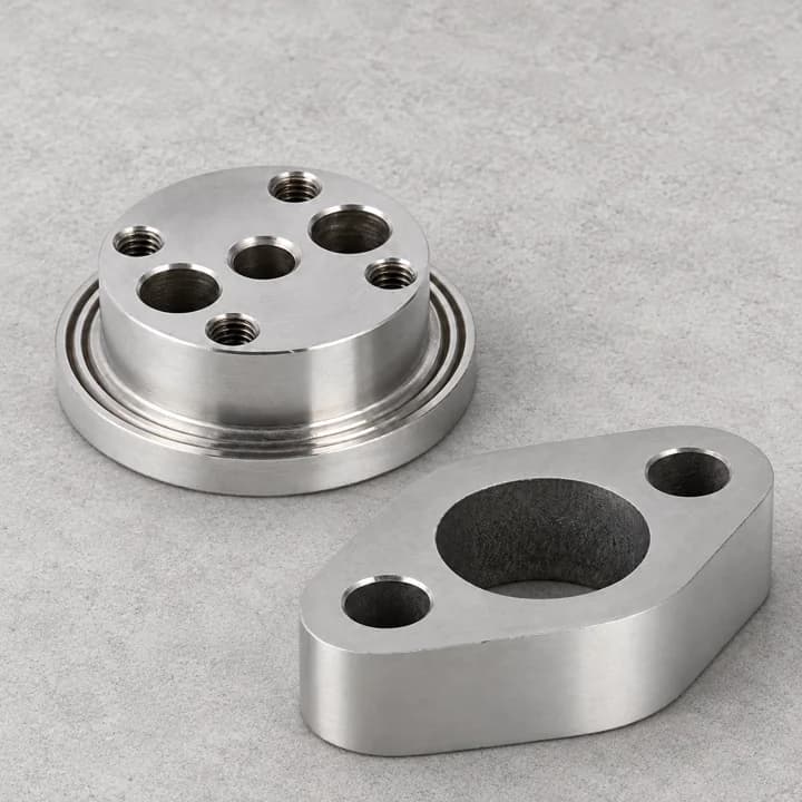
Flanged Components
Circular and two-hole flange forms with stepped faces and mounting openings.
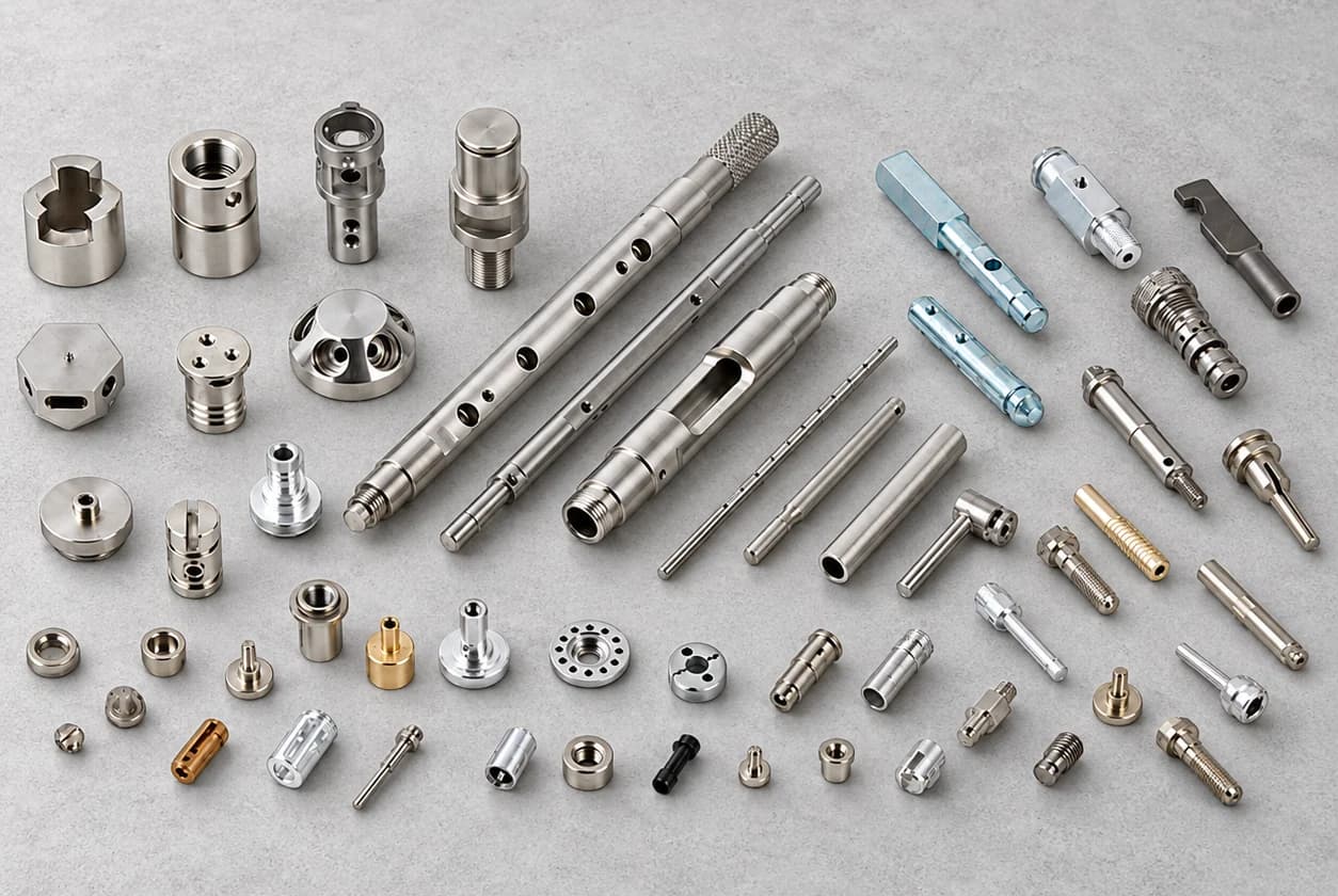
Shafts, sleeves, threaded bodies and mounting features for drawing-based projects.
Circular and two-hole flange forms with stepped faces and mounting openings.
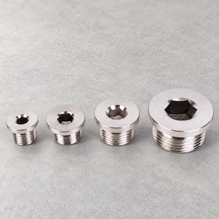
Externally threaded bodies with recessed drive features and low-profile shoulders.
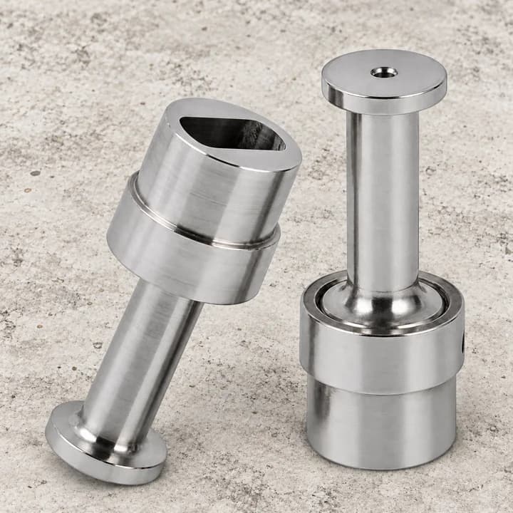
Cylindrical stems with larger end sections, shoulders and central openings.
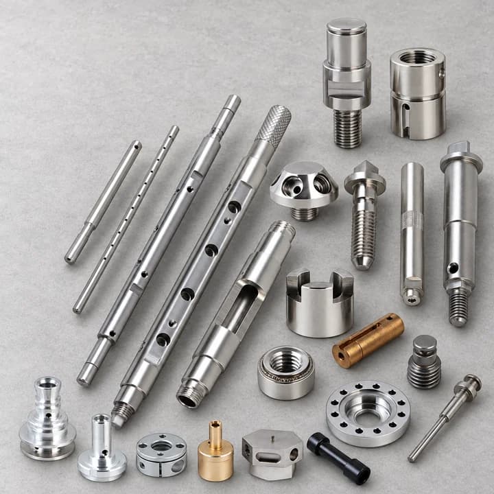
A selection of turned bodies, shafts and small components with varied interfaces.
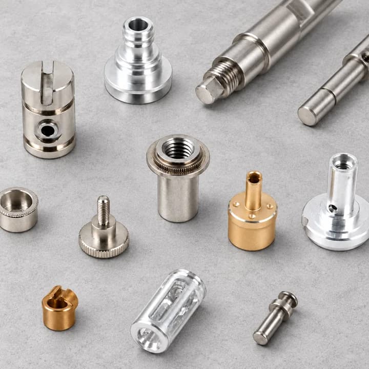
Compact sleeves, pins and flanged bodies with stepped cylindrical profiles.
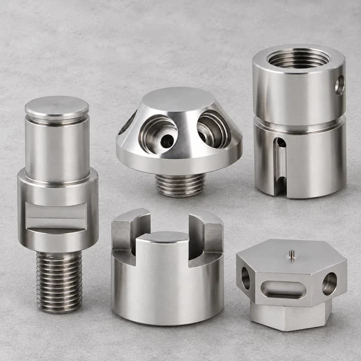
Round bodies combining side openings, slots, external threads and shoulders.
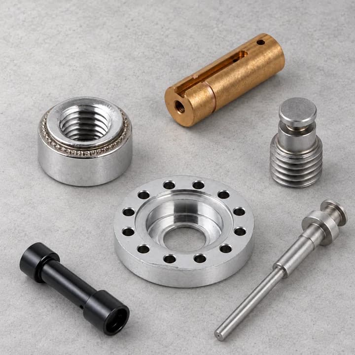
Ring and insert forms with internal openings, flange details and threaded features.
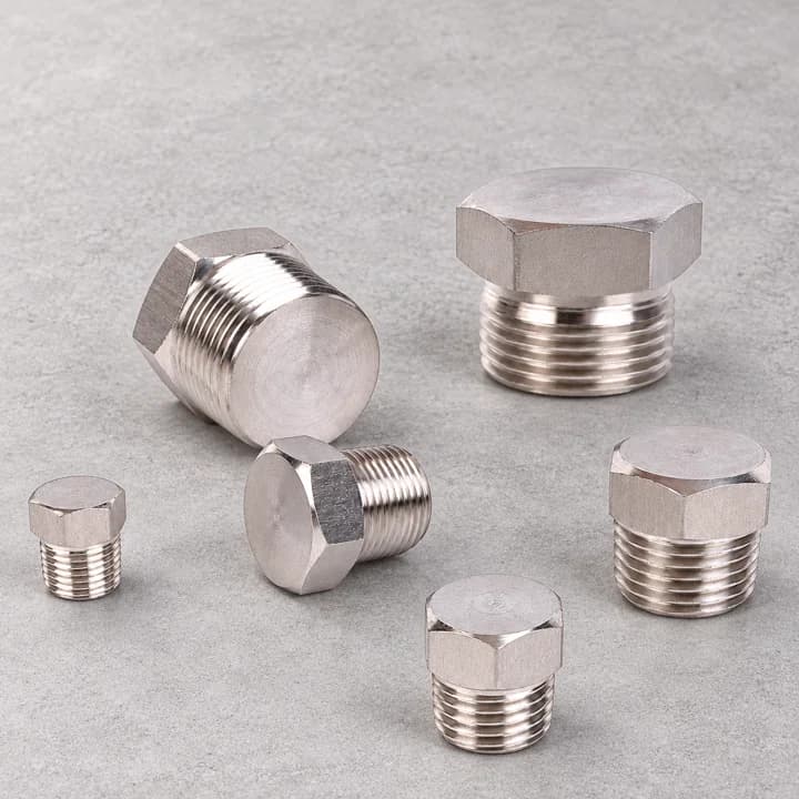
External hexagonal heads paired with short threaded stems in several proportions.
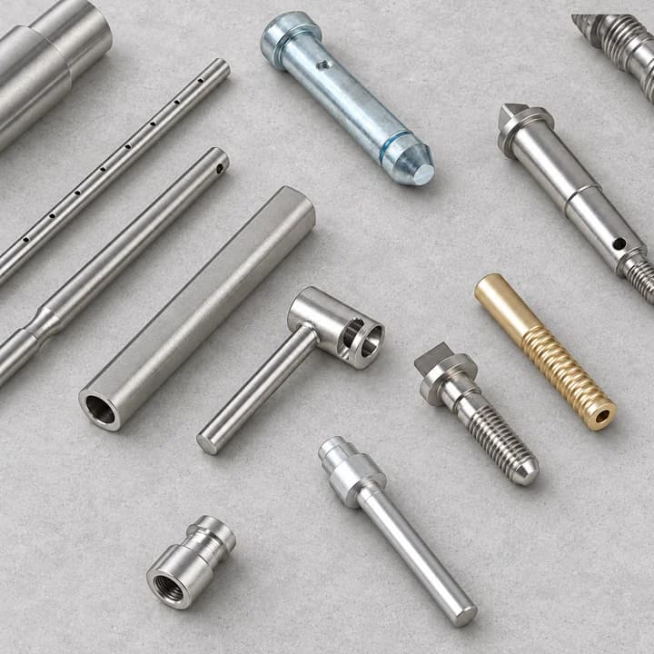
Long cylindrical profiles with stepped diameters, hollow sections or end features.
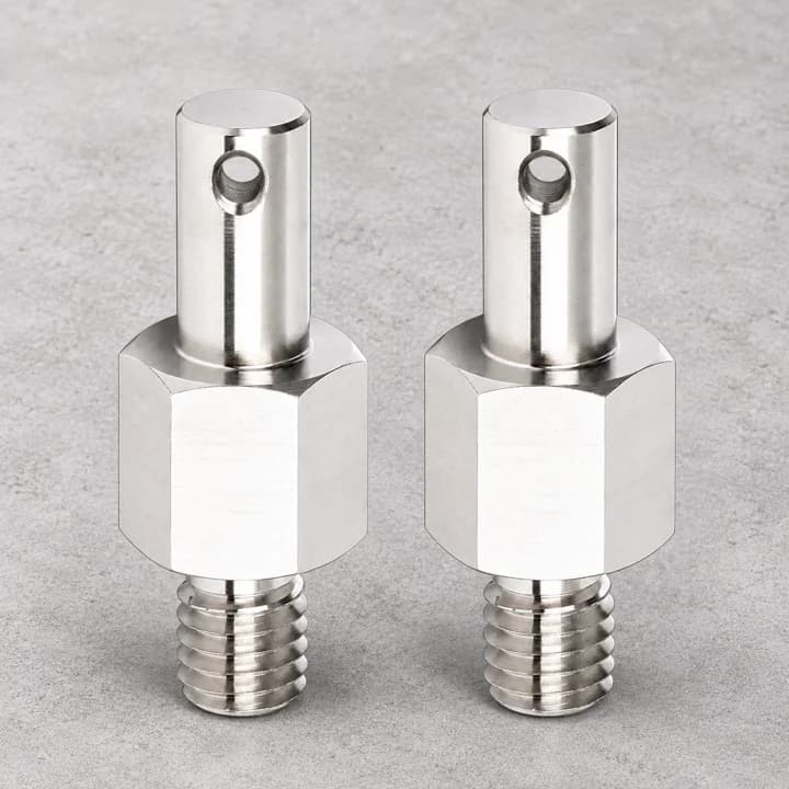
Threaded stems with hexagonal shoulders and slotted upper sections.
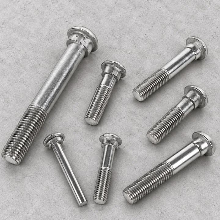
Slim pin forms with broad heads, stepped bodies and threaded ends.
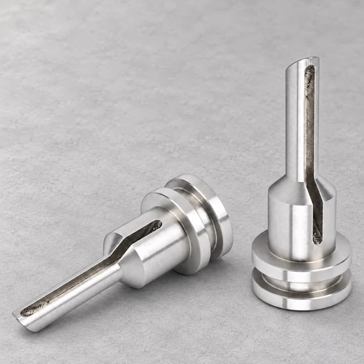
Stepped shafts combining slender stems, circular shoulders and larger end diameters.
Photographs illustrate component forms. Material, coating, dimensions and manufacturing scope are confirmed for your project; appearance alone does not establish a material grade.
Combine the operations your component needs, or discuss a standalone machining project.
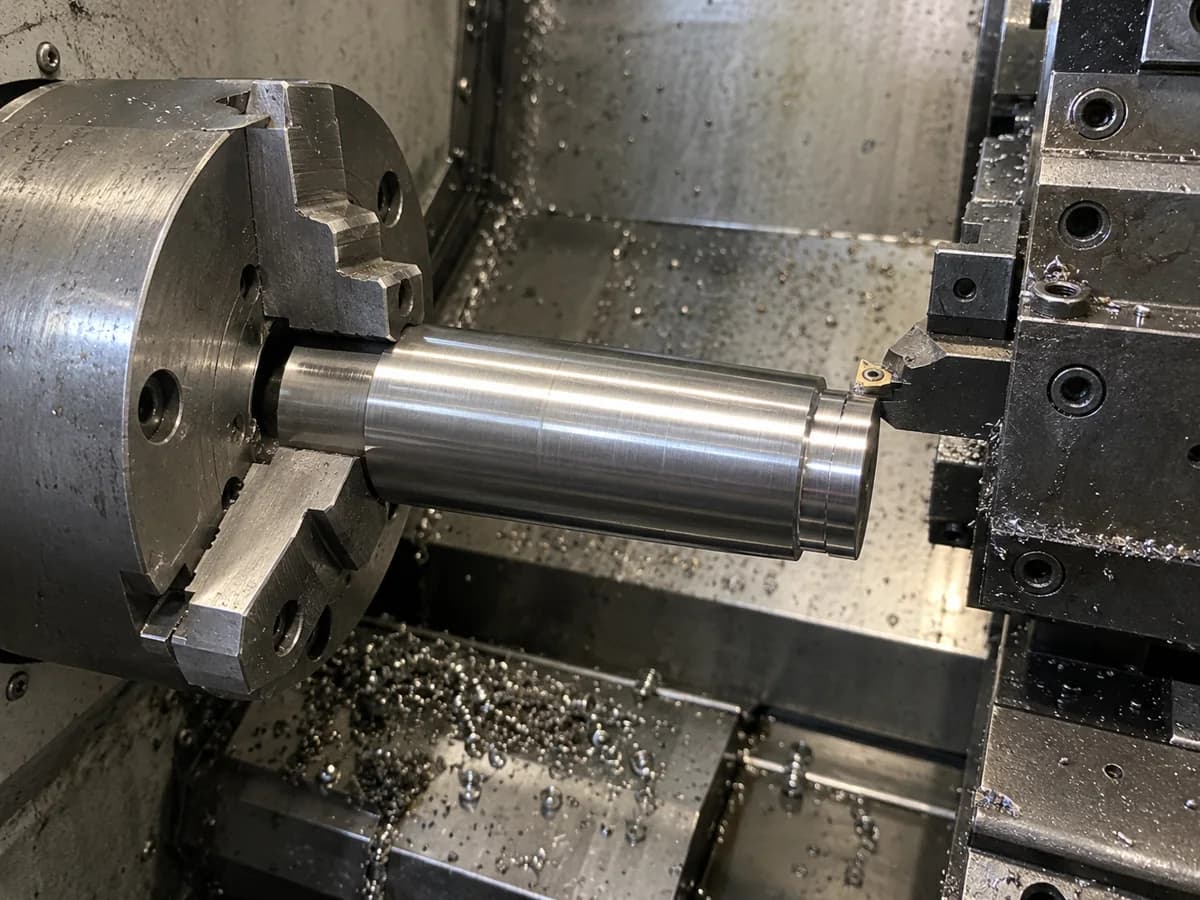
For cylindrical features such as outside diameters, shoulders and bores. Tool access and the required concentric features are reviewed against the drawing.
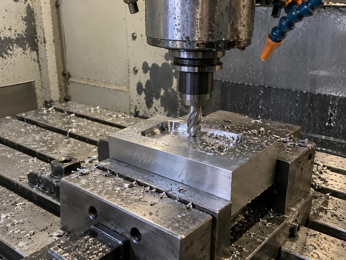
For applicable flat faces, pockets, slots and external profiles. Workholding and the surfaces that locate the component are assessed for the part.
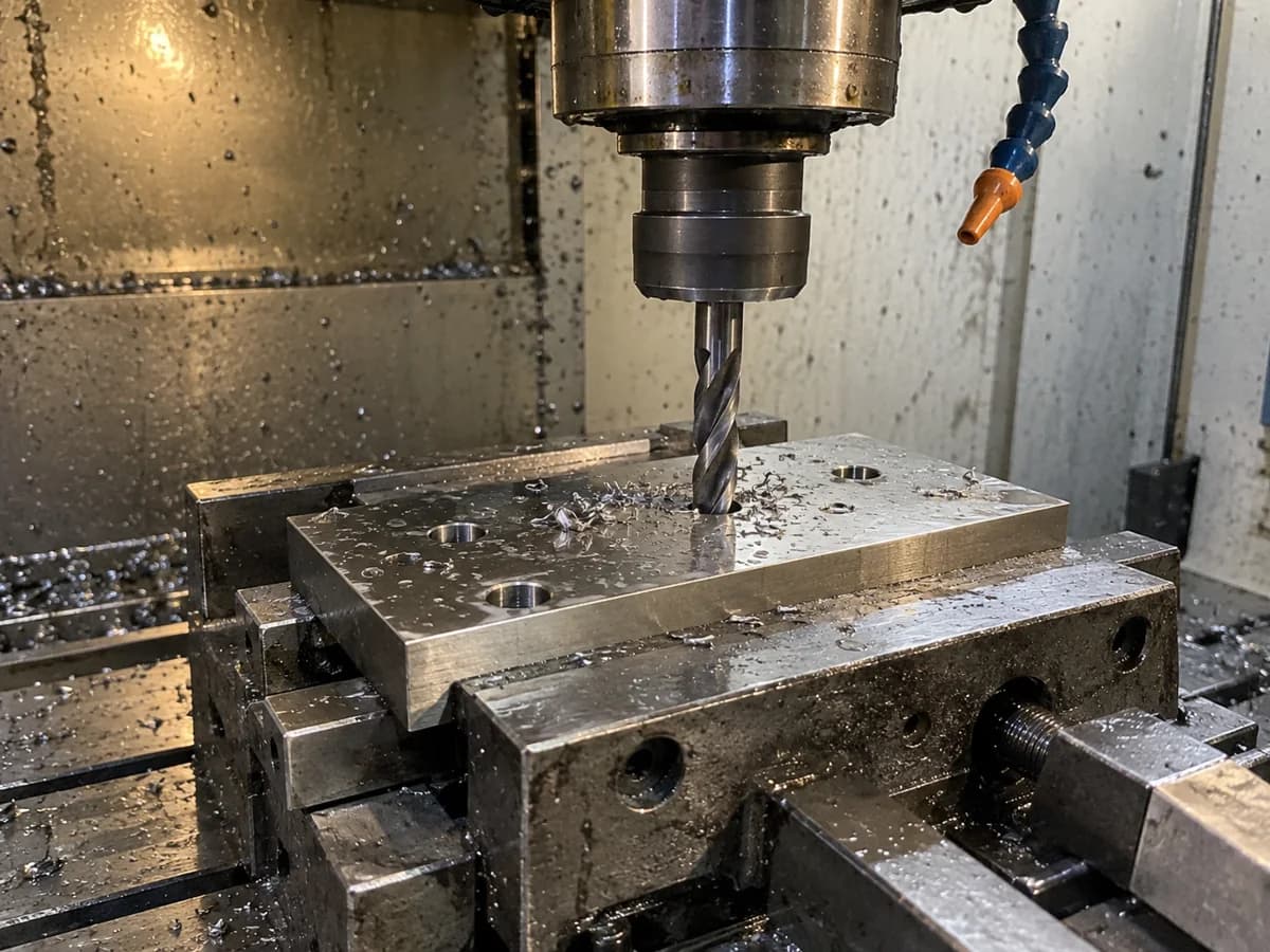
For specified holes in the component. Hole position, depth, diameter and access are reviewed together with the drawing requirements.
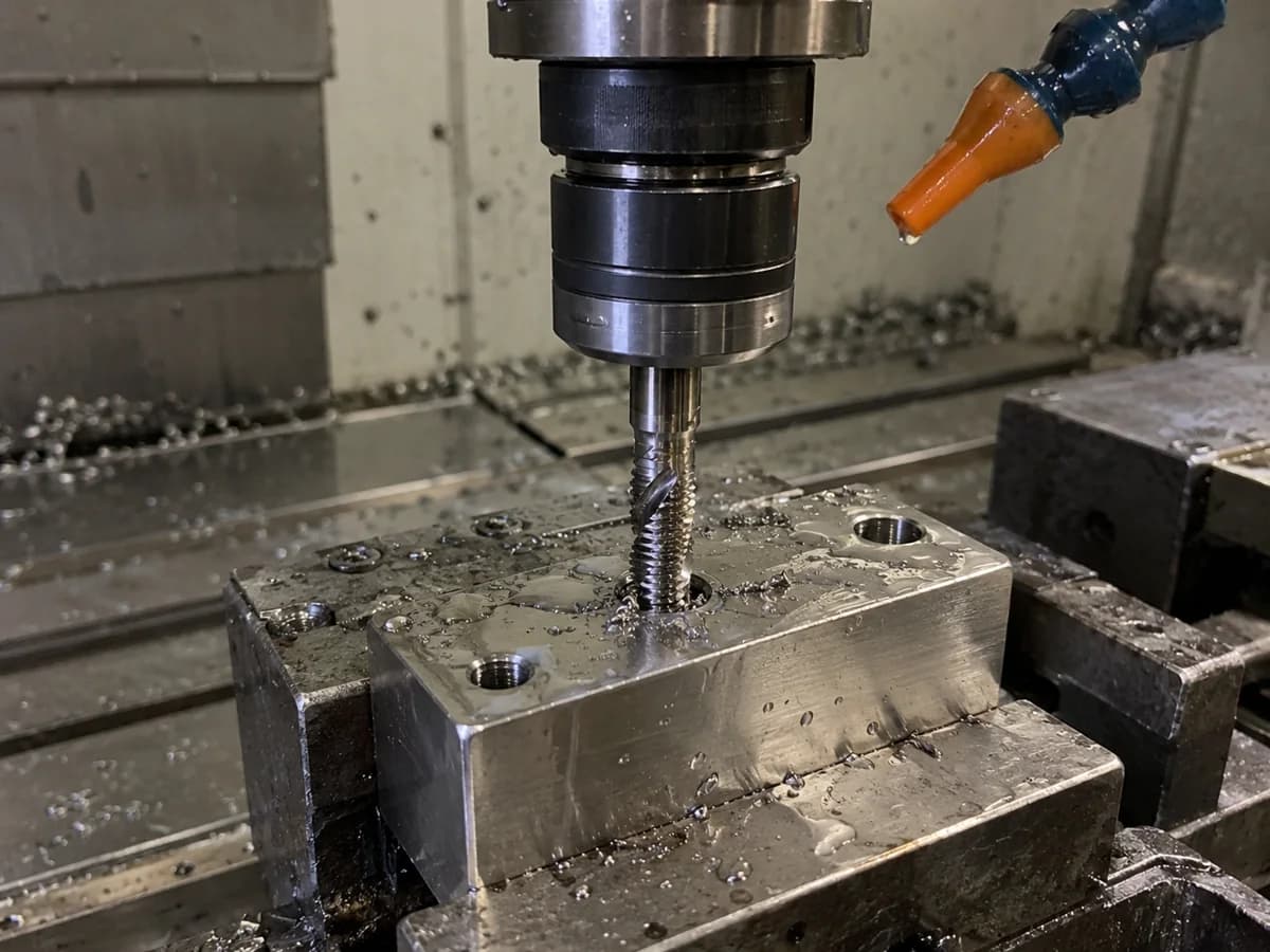
For applicable internal threads in prepared holes. State the thread designation, depth and inspection requirements for review.
AI-generated process illustrations; these images do not document Lastwell equipment or a specific production order.
Send the current drawing revision, your preferred material and the required quantity. Mark critical dimensions and assembly interfaces. A 3D model supports review; the agreed 2D drawing should define acceptance requirements.
These are evaluated for each drawing and project. Include your critical dimensions, required quantity and target date so we can discuss feasibility and quotation terms.
Calipers are used for applicable dimensional checks, and thread plug gauges for applicable internal threads. A factory quality inspection report can be provided. Specify the dimensions and report requirements for review before ordering.
No. We accept independent CNC inquiries for custom parts machined from bar or plate stock.
Share your drawing and requirements. Let’s discuss the manufacturing route.