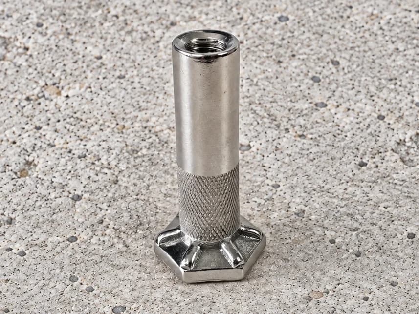
Hex Foot Ferrules
Internally threaded ferrules with a hexagonal foot. Define the body length, thread engagement and base geometry for your concrete connection project.
View product →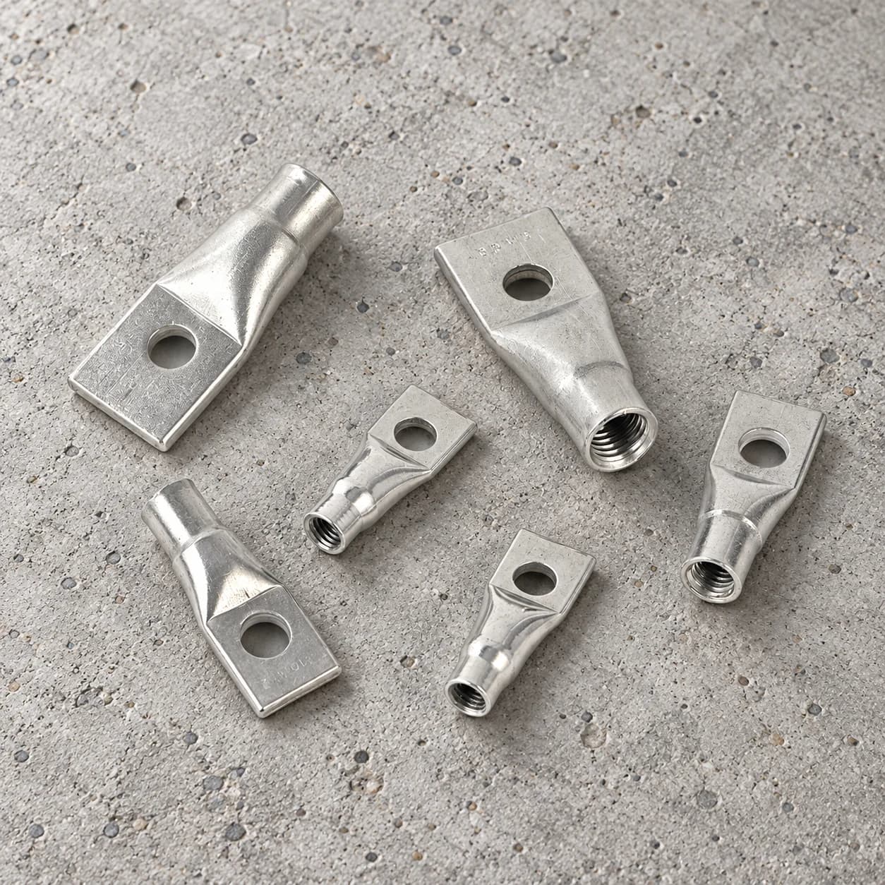
Swipe to explore the product views.
Threaded socket forms with a flattened end and transverse hole. Define the hole position, flat-section dimensions and internal thread for your project.
Share your drawing, material specification and quantity.
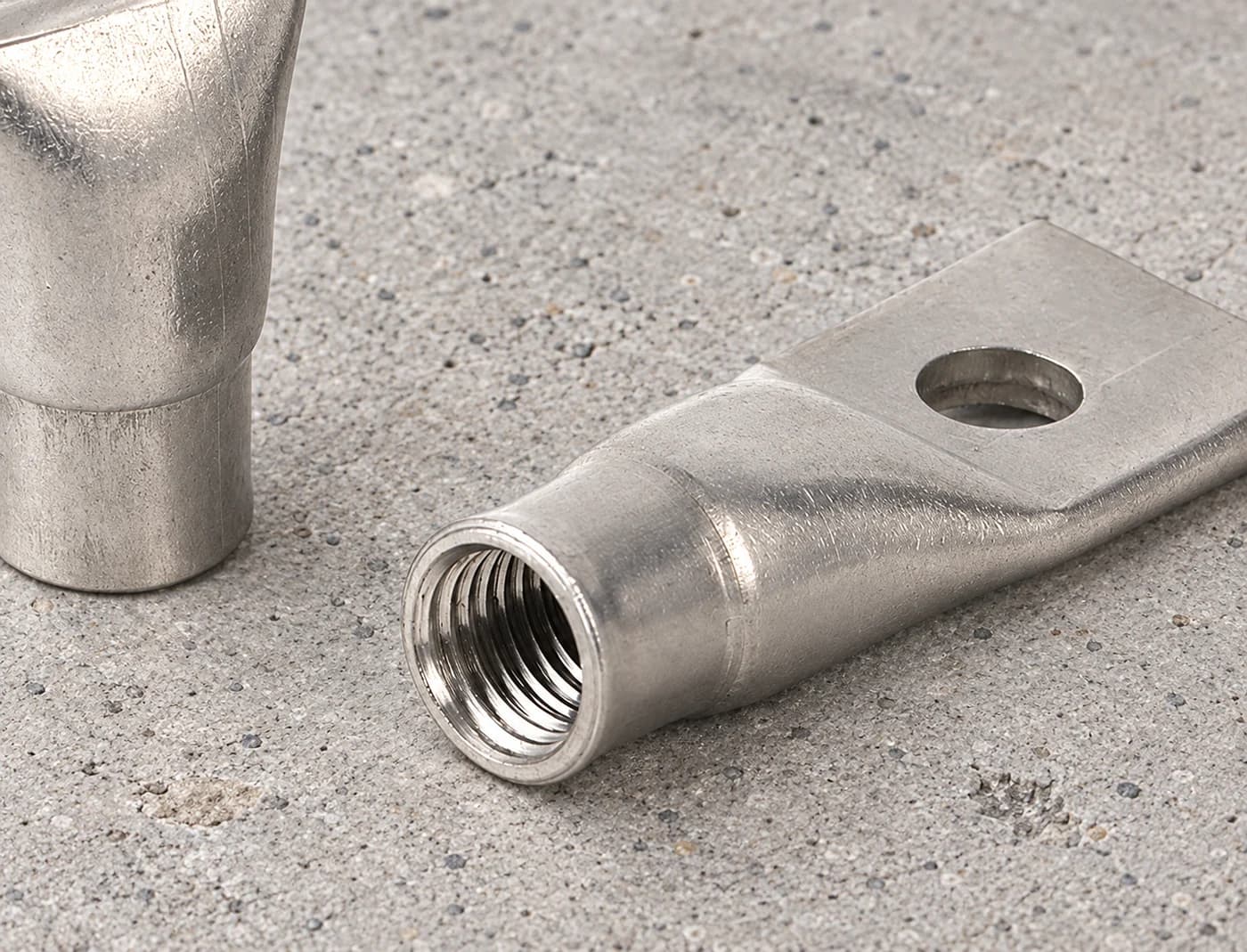
Flat end threaded sockets combine a cylindrical internally threaded opening with a flattened section at the opposite end. A transverse hole passes through that flat section. This shape distinguishes the product from a straight cross-hole socket, a cross-pin insert and a socket attached to a separate base plate.
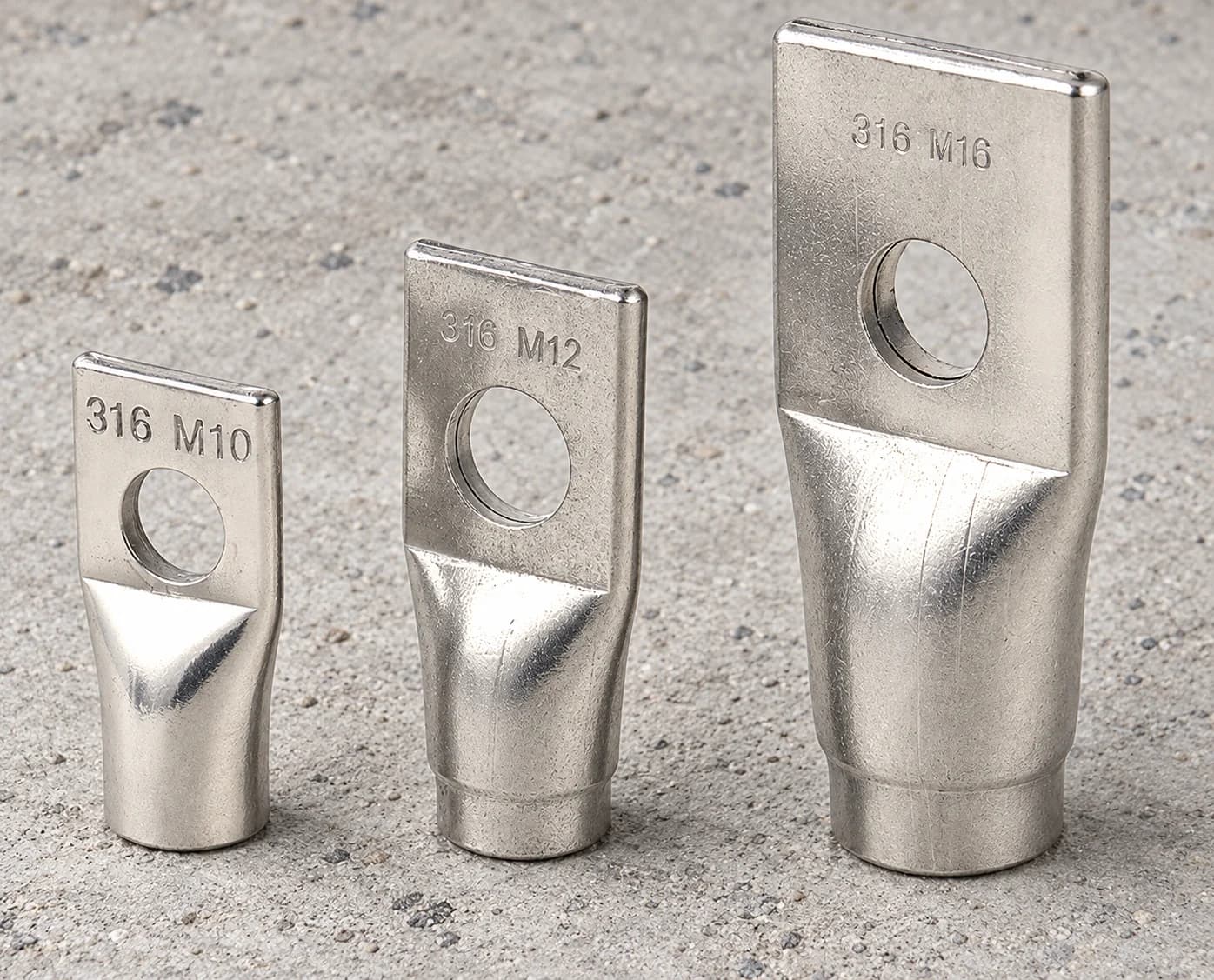
Specify the flat section width, thickness and length, together with the hole diameter and its position relative to the end. The transition from the cylindrical socket into the flat section should also be defined where it affects fit or acceptance.
The cylindrical end requires its own thread designation, usable engagement length and body dimensions. Product markings visible in some images do not replace material documentation or establish the complete purchase specification. The agreed drawing should identify the required finished geometry and material.
Define the intended fixing arrangement alongside the component geometry. The flattened section, hole and threaded end need to be considered within the complete connection drawing. State whether the inquiry concerns a fixing component or a lifting-related project, and include the corresponding acceptance requirements.
Provide any specified bar or mating element and the relevant project documents. A lifting-related inquiry requires the complete approved arrangement and validation scope; this description does not assign a lifting capacity or approve a reinforcement detail.
Tolerances, order quantity and lead time are assessed for the project.
Send your drawing →No. Similar-looking forms may be described for fixing or lifting. The specified product, approved arrangement and supporting validation determine the intended use.
No bar is included by implication. Specify any bar or mating component, its dimensions and the required assembly scope in the inquiry.
Markings can help identify an example, but material acceptance should follow the agreed specification and documentation. They do not establish the material of every item in the range.
Share your drawing and requirements. Let’s discuss the manufacturing route.
Compare other component forms for your drawing requirements.
Internally threaded ferrules with a hexagonal foot. Define the body length, thread engagement and base geometry for your concrete connection project.
View product →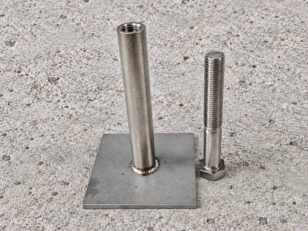
Threaded socket components with a square flat base plate. Specify the plate dimensions, socket height and connection details for project review.
View product →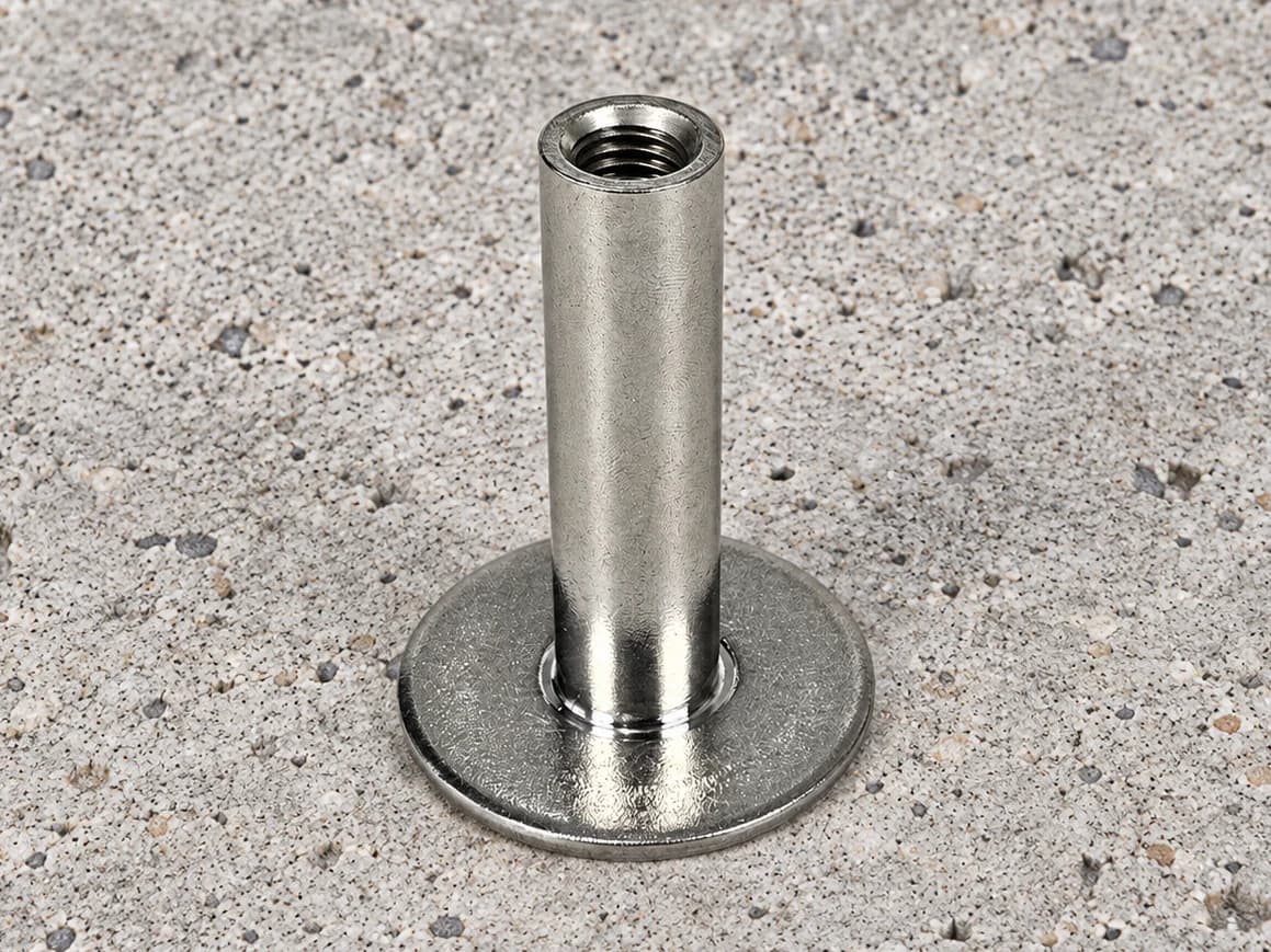
Internally threaded sockets with a circular plate base. Define the plate diameter, socket position and thread details for a drawing-based inquiry.
View product →