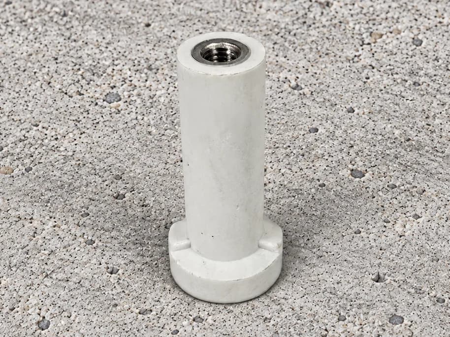
Round-Foot Concrete Ferrules
Round-foot ferrule forms with a visible internal thread. Define the thread system, body proportions and base details before selecting the final component.
View product →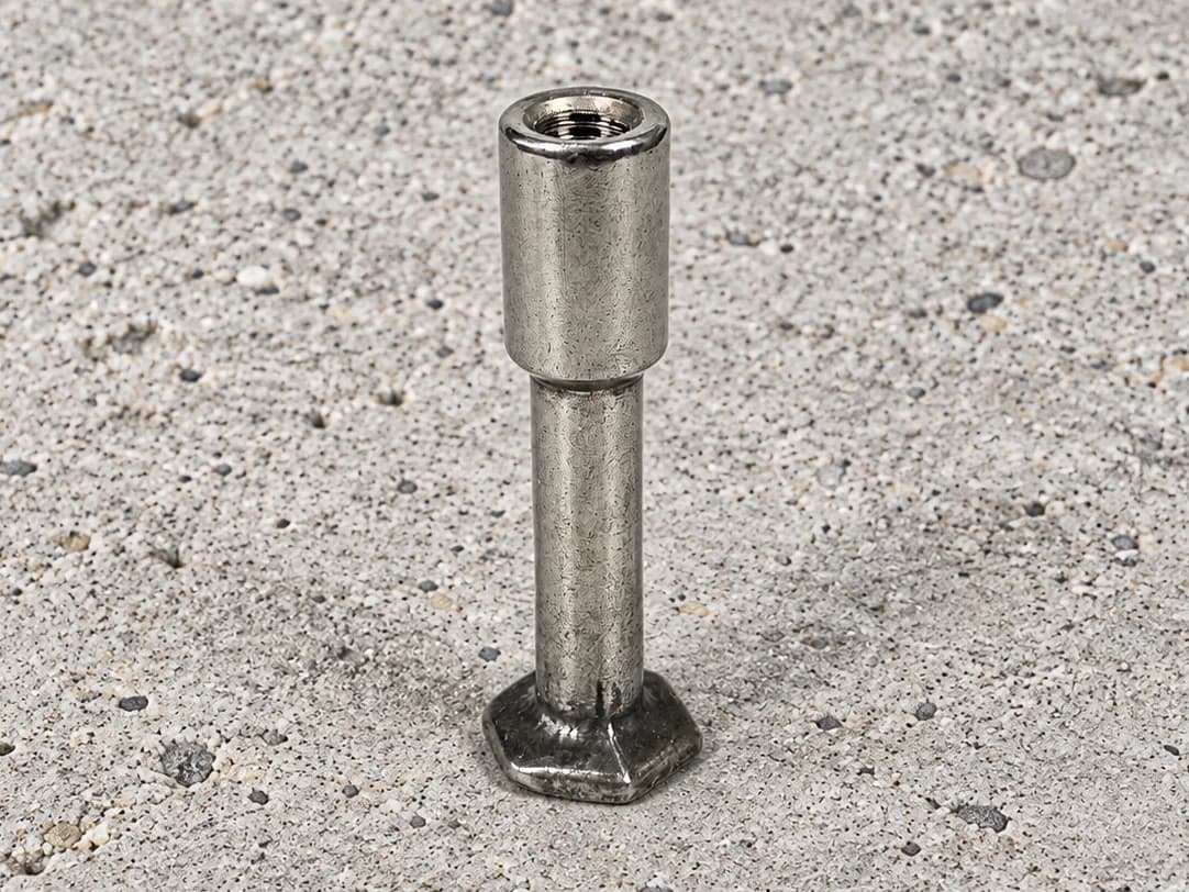
Swipe to explore the product views.
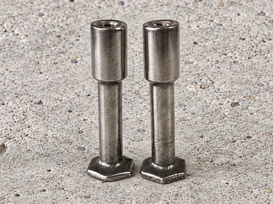
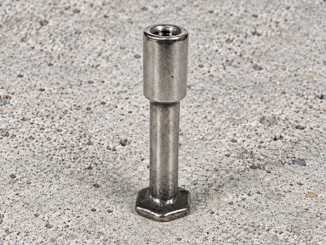
Foot anchor components with an enlarged threaded head, reduced shank and polygonal foot. Specify each section and the complete assembly requirements.
Share your drawing, material specification and quantity.
Internally threaded foot anchor components have a stepped profile: an enlarged socket head at the connection end, a narrower shank and a polygonal foot. This visible change in section is the main difference from the straight-body ferrules elsewhere in the product range.
The enlarged head contains the internal thread. Below it, the slimmer shank extends to the foot. A useful component drawing defines each diameter, section length and transition instead of describing the part only by total length and nominal thread size.
The photographs show a smooth-looking shank rather than a visibly ribbed reinforcement bar. They do not establish whether the component is one piece, joined from separate parts or produced by a particular forming route. Specify the required construction and material for each section, including the joining and inspection criteria where relevant.
For lifting-anchor procurement, provide the approved component or assembly drawing, the intended connection and the required validation documents. A threaded foot form is not itself a load approval, and an internally threaded head does not establish compatibility with a particular lifting attachment.
Socket engagement, shank geometry and foot geometry should be reviewed together. The drawing should make clear which surfaces are functional, which dimensions are critical and which records are required for acceptance of the manufactured component.
Tolerances, order quantity and lead time are assessed for the project.
Send your drawing →That cannot be confirmed from the supplied photographs. The visible shank is smooth-looking; its material, forming method and construction need to be specified.
The images do not establish the material of each section. State the required material arrangement and supporting documentation on the drawing or purchase specification.
No. The thread form, engagement, component geometry and approved assembly requirements must be reviewed together.
Share your drawing and requirements. Let’s discuss the manufacturing route.
Compare other component forms for your drawing requirements.
Round-foot ferrule forms with a visible internal thread. Define the thread system, body proportions and base details before selecting the final component.
View product →
Internally threaded fixing inserts with a transverse pin projecting from both sides. Define the pin location, projection and joining requirements by drawing.
View product →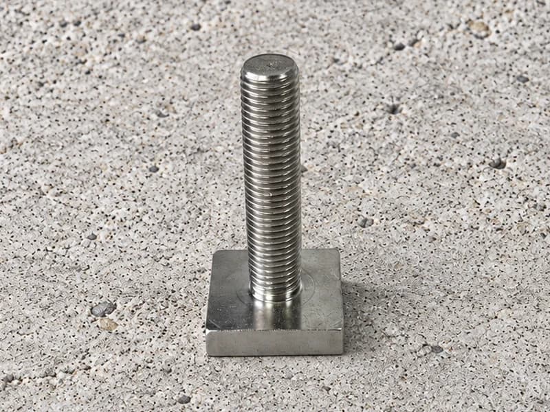
Externally threaded fasteners with a square flat head. Define the head footprint, thread and shank dimensions to suit the specified mating assembly.
View product →